2D Physics Engine From Scratch (Jack in Box)
Overview
This project simulates planer multi-body impact dynamics of a jack bouncing around inside a box. In this simulation, external forces are applied to the box as input to the system. The primary forces applied are a sinusoidal rotational force that rotates the box back and forth and a vertical support force that stops the box from falling. The jack is in free-fall, and bounces off the walls of the box.
Video demo
System Diagram
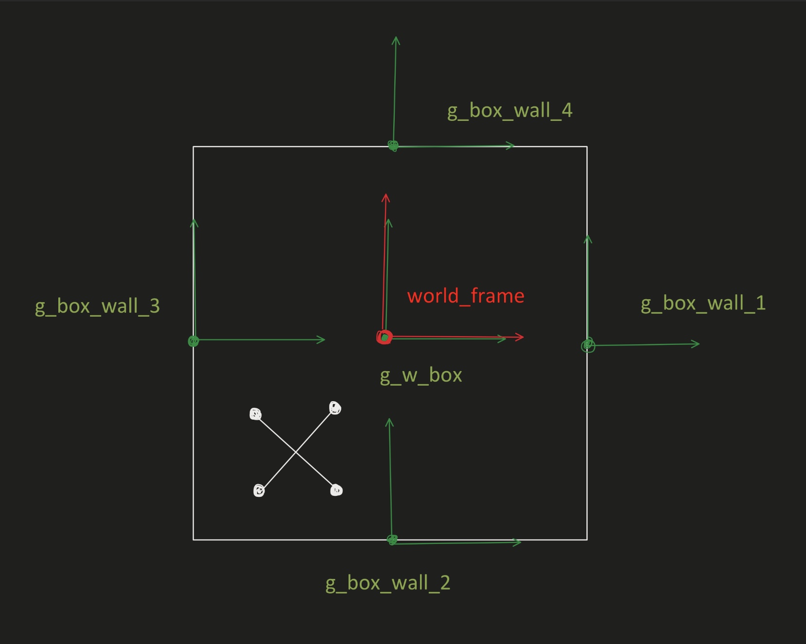
Below are diagrams showing the system used in this assignment. First, the frames and transformations used to simulate the box in this project are as follows:
- world_frame
- g_w_box: the center of the box relative to the world_frame
- g_box_wall_1, 2, 3, 4: the walls of the box relative to the g_w_box frame

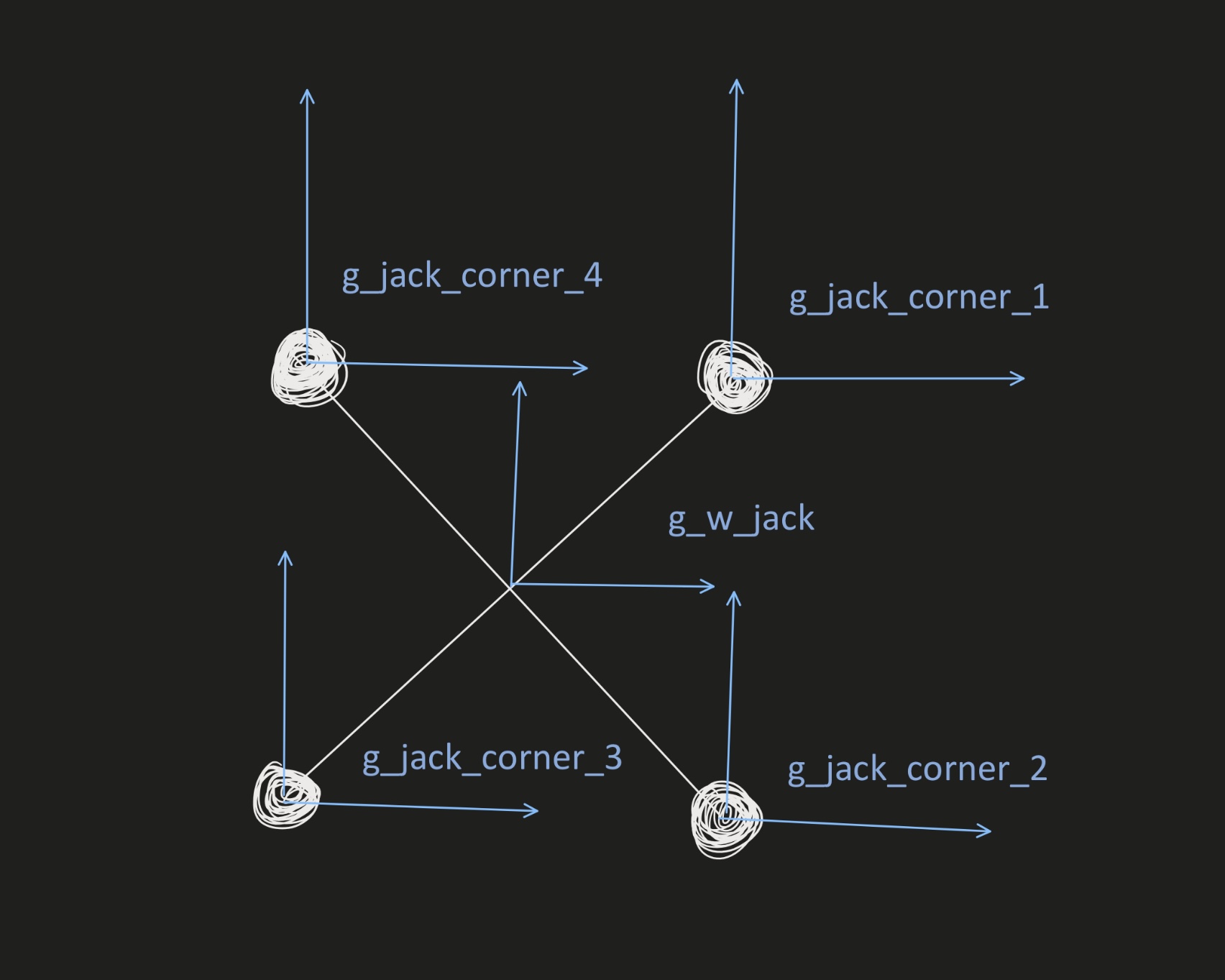
For simulating the jack, the following are used:
- g_w_jack: the center of the jack relative to the world_frame
- g_jack_corner_1, 2, 3, 4: the corners of the jack relative to the g_w_jack frame

Parameters
- side_length_box: The length of each side of the box (default = 10)
- mass_box: The total mass of the box (default = 3)
- length_jack: The overall length of one of the jack massless rods (default = 1)
- mass_jack: The total mass of the jack (default = 1)
- External Forces: There are two external forces applied in this simulation:
- A force applied to the box in the positive y-direction to counter the force of gravity. It is equal to the weight of the box and jack combined.
- A constant rotational torque applied to the box. The torque is given by the equation torque = a * mass_box * g, where a is a constant (default = 1).
- Initial Configuration: In the initial configuration used, the box is centered at (0, 0) with a theta angle of 0. The jack starts at (3.5, 0) with an initial angle of pi/3 radians.
Algorithm Description
State Variable
The current state of the system is stored as a vector, q, which contains the following variables describing the position and orientation of the box and the jack relative to the world frame:
- x_box: the x coordinate of the center of the box
- y_box: the y coordinate of the center of the box
- theta_box: the current angle of the box about the z axis
- x_jack: the x coordinate of the center of the jack
- y_jack: the y coordinate of the center of the jack
- theta_jack: the current angle of the jack about the z axis
Velocities and accelerations for the two objects are also found by taking the first and second time derivatives of q. Velocities are stored in the vector qdot and accelerations in the vector qddot.
Euler Lagrange
To solve for the dynamics of the objects in the system, first the Euler Lagrange equations and the external force were found. The following steps are used to find Euler Lagrange equations:
- Calculate body velocities of each object. This is calculated using the frames at the centers of box and the jack.
- Find the 6 by 6 mass inertias of both objects. Both the jack and the box are simplified as a model with 4 point masses attached to them
- Calculate the total kinetic energy in the system (KE). Since these objects are translating as well as rotating, we need to calculate the both the linear and rotational kinetic energy for both objects, then sum them to find the total KE for the system.
- Calculate total potential energy for the system (V). In this system, gravity is the only source of potential energy. Potential energy for both objects is calculated relative to the origin of the world frame, then summed to find the total.
- Compute the Lagrangian of the system using the following equation: L = KE - V
- Compute the force matrix based on the forces applied to the system. The force matrix contains the external forces in the x and y directions and the torque about z applied to both the box and the jack.
- Find the Euler Lagrangian equation based on Lagrangian and the force matrix, using the equation F = ddLdqdot - dLdq, where:
- dLdq: the derivative of the Lagrangian with respect to q
- ddLdqdot: the time derivative of the derivative of the Lagrangian with respect to qdot
Constraint Equations
The constraints are defined between each corner of the jack and each wall of the box; the corners of the jack cannot pass through the walls of the box. As a result, there are a total of 16 constraint equations defined. The constraint variable phi is defined as the expression of the distance between the two impacting objects. As a specified jack corner and wall of the box move closer together in the simulation, the phi value associated with that specific constraint equation approaches zero. When phi gets close enough to 0 (for this simulation, a threshold of 0.1 was used), the two objects are considered to have collided.
Impact Updates
After two objects collide, their states are updated to reflect the results of the impact. The following steps are used to solve for impact updates:
- Create two sets of dummy variables for all the state variables. One set of dummy variables is for before impact and the other is for after impact.
- Calculate Hamiltonian, dLdqdot, dphidq for the system
- Substitute dummy variables to those equations for both before and after impact
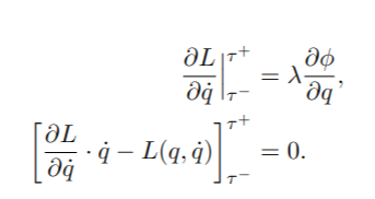
- Construct and solve for the equations based on the following formula:
