Design of a 3D Printed Cycloidal Robot Actuator for a Quadruped Robot
Overview
The goal of this project was to develop an actuator for future use in a quadruped robot. The actuator was 3D printed, and used a cycloidal drive to transmit power from a 5008 brushless motor to the output. The design also incorporates a built in encoder for tracking position. It was designed to be economical to produce while still being relatively small and light - these goals were met, with an estimated cost of <$60, a mass of 454g, and ⌀80mm x 67mm size. It was also able to achieve >12 Nm of torque during testing. Based on this success prototypes for a quadruped robot based on this design were built and run through initial testing.
Design Targets
The goals for this project were primarily around cost and manufacturability while maintaining some key features for a dynamic walling robot:
- Cost: The overall actuator should cost less than $100, not including motor driver
- Manufacturability: The actuator should be designed to be largely 3D printed for ease and accessability of manufacturing. Bearings, hardware, electronics, motor can be purchased, but other components should be made using 3D printing,
- Torque: Torque output >10 Nm.
Design
Cycloidal Gearbox A cycloidal gearbox is a mechanical device designed for power transmission, utilizing a cam mechanism with lobed cams and bearings. This design minimizes backlash, ensuring precise torque transmission. It is characterized by its compact size, high torque density, and shock-load resistance. These features make it perfect for this application.
The cycloidal gearbox operates on the principle of eccentric cams and needle bearings. The input shaft, connected to an eccentric cam, rotates within a lobed cam track. This eccentric motion causes the needle bearings to move along the lobes, resulting in an oscillating, or cycloidal, motion. The output shaft is connected to pins that follows the cycloidal path, transmitting the motion to the output stage. The gearbox’s structure inherently minimizes backlash, as the engagement of the bearings with the cam surfaces ensures continuous contact, contributing to its precision and reliability in power transmission applications. Using two cycloidal gears stacked on top of each other and set 180 degrees out of phase can help reduce vibrations from the drive. The second gear helps balance many of the vibrations from the oscillation of the gears.
Selecting the correct ratio for this gearbox was key. For the dynamics and functionality of the robot, it was important to maintain a back-drivable actuator, where the motor could easily be spun by twisting the actuator. After some preliminary testing of different gears, a ratio of 19:1 was selected. This was the highest tested ratio that could still be easily back-driven. Below is an CAD screenshot of the cycloidal gears used in this project.
3D Printed Components The CAD screenshots below show the 3D printed parts used in this design along with stand ins for some of the purchased parts. Non-printed parts are shown in red.
Because of the speed and ease of use of 3D printing, I was able to go through many iterations of the design. One area that took significant refinement was the tolerancing of the cams and lobes of the cycloidal gearbox. If the tolerances were too small, the gearbox had excessive torque that made back-driving difficult or impossible. However, if the tolerances were too loose, the actuator would have no precision. Eventually a range was found that satisfied both conditions. It was also noted that the actuators went through a break-in period, where the gearbox became much “looser” as some of the imperfections in the 3D prints were worn down. As a result, new actuators were printed with slightly tight tolerances, and were run through a break in procedure after assembly.
Encoder PCB To precisely control the position of the actuator, the motor controller requires feedback about the position of the motor using an encoder. For this project, to maintain the compact design of the actuator, I decided to make a custom encoder PCB for convenient mounting of the encoder. The encoder was mounted on the back side of the motor, on the outside surface of the actuator. A magnetic AS5045B encoder was used, which could function as an absolute or relative encoder. Below is a PCB for relative A/B/Z encoder output. A second board was also developed which used SPI output to provide an absolute encoder position.
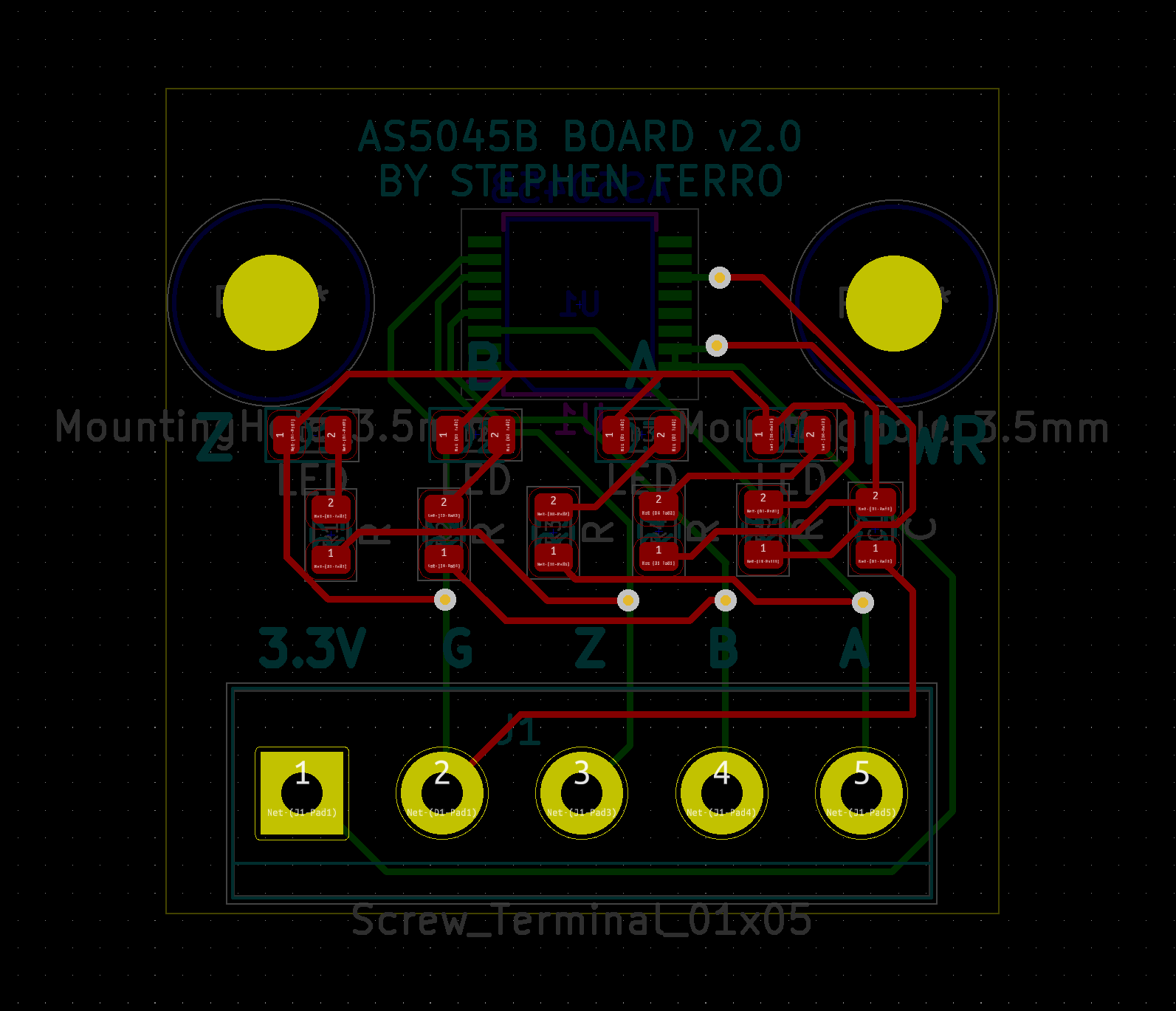
A magnet was glued to the back end of the motor shaft, and the encoder was positioned about the magnet due to it’s mounting. When the motor spun, the encoder could measure and output the rotational speed of the shaft.
Testing
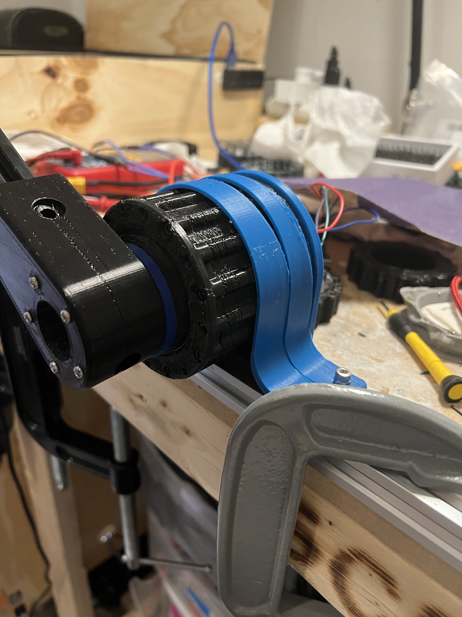
Two different types of torque testing were performed with this actuator. First, a series of static torque tests were performed. For these tests, a lever arm made from an aluminum extrusion was attached to the actuator, and the actuator was secured. When the actuator finally failed, it was due to the motor controller not being able to supply enough current to the motor. The test setup is shown below.
The procedure for the tests was as follows:
- Position the lever arm horizontal.
- Enable closed loop control on oDrive motor controller so lever arm holds position.
- Hang the specified weight at the specified distance from actuator centerline.
- Pass condition: actuator can support weight without collapsing. Deflection is allowed as long as the arm returns to neutral position when weight is removed.
- Repeat with the next weight and distance conditions until the actuator fails to support weight.
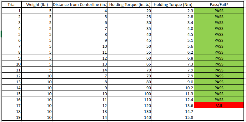
And the results of the test are below. The actuator was able to support over 12 Nm in the static test.
The second type of testing was dynamic testing. This involved requiring the actuator to lift a load from horizontal to a higher position. The procedure was as follows:
- Position the lever arm horizontal.
- Enable closed loop control on oDrive motor controller so lever arm holds position.
- Hang the specified weight at the specified distance from actuator centerline.
- Advance the actuator two motor revolutions (from position 0 to position 2).
- Pass condition: actuator is able to complete the two revolution movement, deflection is allowed as long as the arm returns to the neutral position when the weight is removed.
- Repeat with the next weight and distance conditions until the actuator fails to support weight.
Below is a video of the dynamic testing.
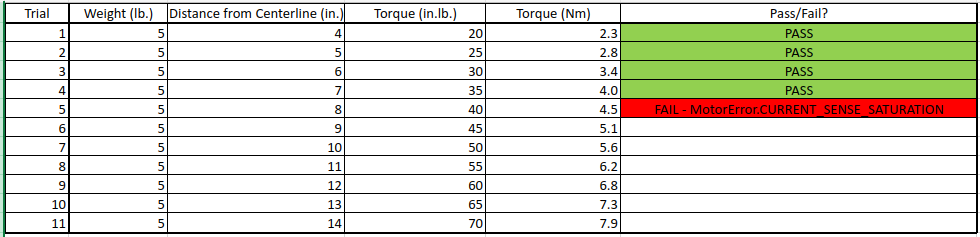
And the results of the test are below. The actuator was not able to support as much as in the static test. This was likely due to an issue with the tuning parameters on the motor controller. With more tuning, I suspect it could lift more weight.
Future Development
This actuator was designed for use in a quadruped robot, so once a functional prototype was up and running, I incorporated it into a prototype leg for testing. The leg used two actuators, one controlling the knee and one controlling the hip. When constrained on a vertical slider as shown below, the leg was able to do basic motions, such as standing and sitting.
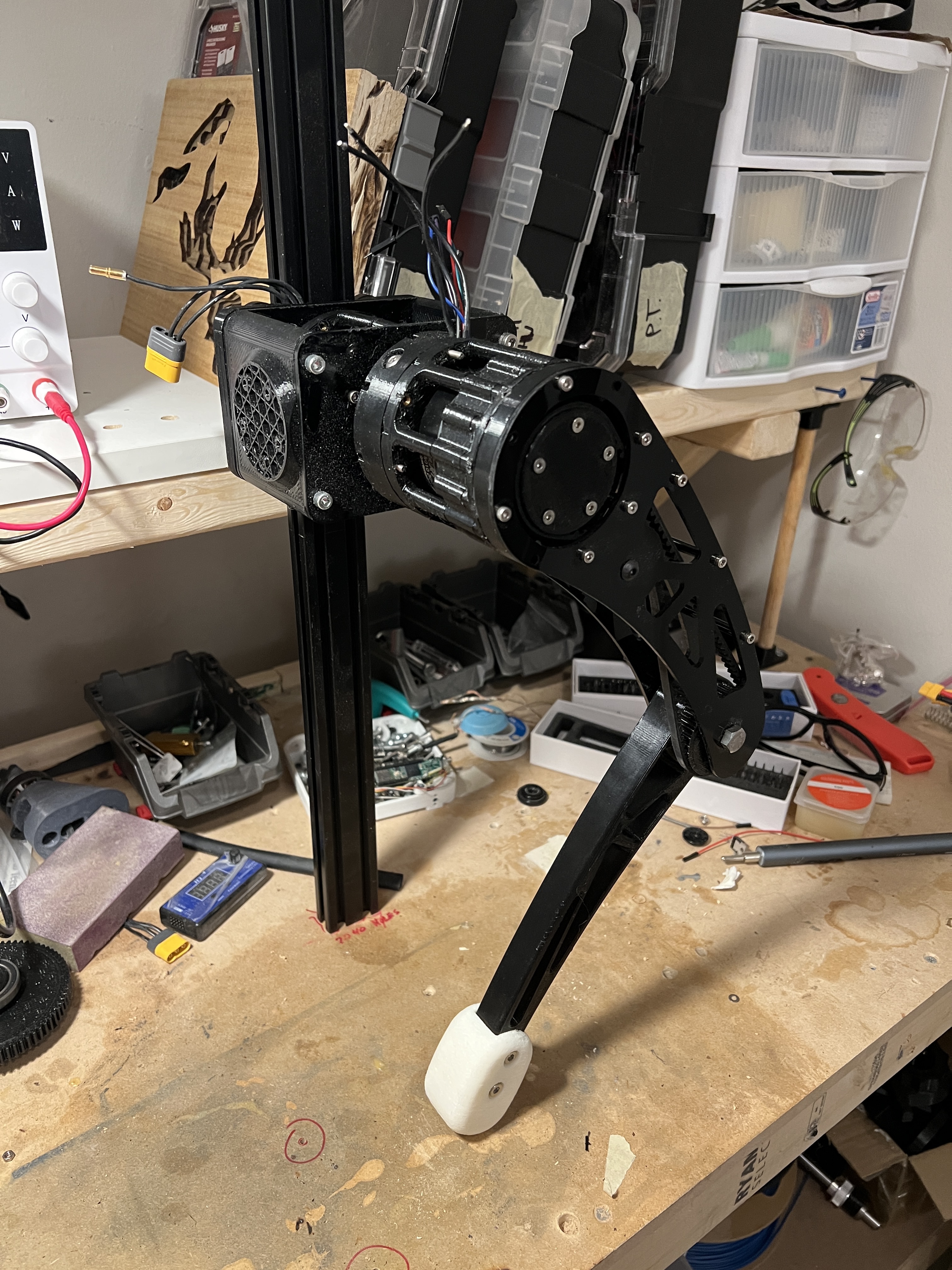
Unfortunately, due in part to damage to the motor controller, progress on this project stalled. I hope to work more on this in the future. Below is a preliminary design for a quadruped built using 12 of these actuators.